MV2 — VRF M&V System

MV2 — VRF Measurement & Verification (M&V) system.

MV2 independently measures the real-time cooling capacity, power consumption and COP of VRF systems, providing reliable performance data under actual operating conditions.

Real time Cooling capacity, power consumption and COP calculation
2 options Permanent monitoring or non-intrusive spot measurement
All brands Compatible with VRF systems from different manufacturers
≤10% Measurement uncertainty verified by A*STAR’s National Metrology Centre
How it works

Measure actual VRF performance.

MV2 measures the refrigerant and electrical parameters needed to determine the actual cooling performance of a VRF system.

Sensors installed around the outdoor unit collect refrigerant flow, temperature, pressure and electrical power data. MV2 processes these readings to calculate cooling capacity and COP continuously, providing a clear picture of system performance under actual operating conditions.

Measurement options

  • Permanent monitoring. An intrusive mass flow meter provides continuous measurement for long-term monitoring and performance optimisation.
  • Non-intrusive measurement. An externally mounted ultrasonic flow meter supports temporary studies and on-demand spot measurements with minimal disruption to the existing system.
01 Measure refrigerant conditions

Temperature and pressure sensors measure the refrigerant conditions on both the liquid and gas sides of the VRF system.

02 Measure refrigerant flow

A mass flow meter or non-intrusive ultrasonic flow meter measures the refrigerant flow required to determine cooling capacity.

03 Measure electrical power

The system records the power consumed by the compressor and condenser fans.

04 Calculate and record performance

MV2 calculates cooling capacity, electrical consumption and COP in real time. The results can be viewed, downloaded or integrated with a Building Management System.

MV2 sensor deployment

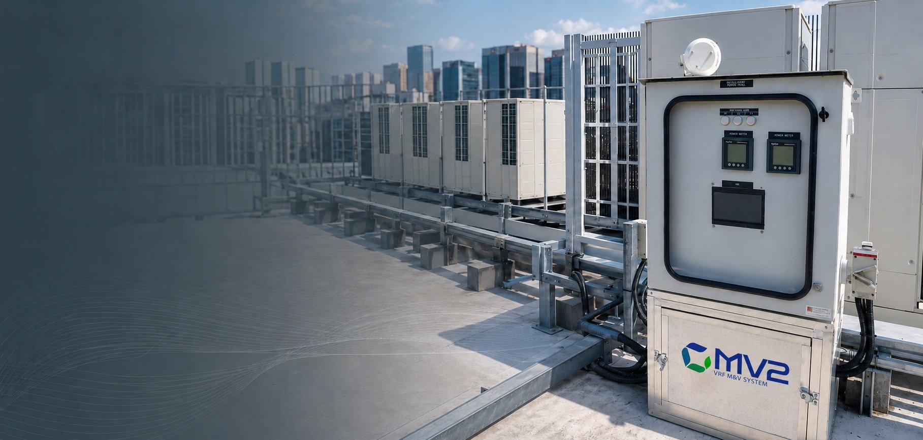
MV2 collects refrigerant and electrical measurements from the VRF system to calculate cooling capacity, power consumption and COP in real time. Select any photograph to open it at full size.

Benefits

Make VRF performance measurable.

  • Independently verifies actual VRF performance.
  • Calculates cooling capacity and COP in real time.
  • Identifies inefficient operation and performance decline.
  • Supports system tuning and energy optimisation.
  • Uses measured data instead of manufacturer estimates.
  • Supports Green Mark M&V requirements.
  • Suitable for permanent monitoring or spot measurements.
  • Compatible with new and existing VRF systems.
Measured, not estimated

From estimated performance to measured results.

VRF performance is often assessed using manufacturer data or indirect calculations. MV2 measures the system under actual operating conditions, allowing performance issues and optimisation opportunities to be identified using real evidence.

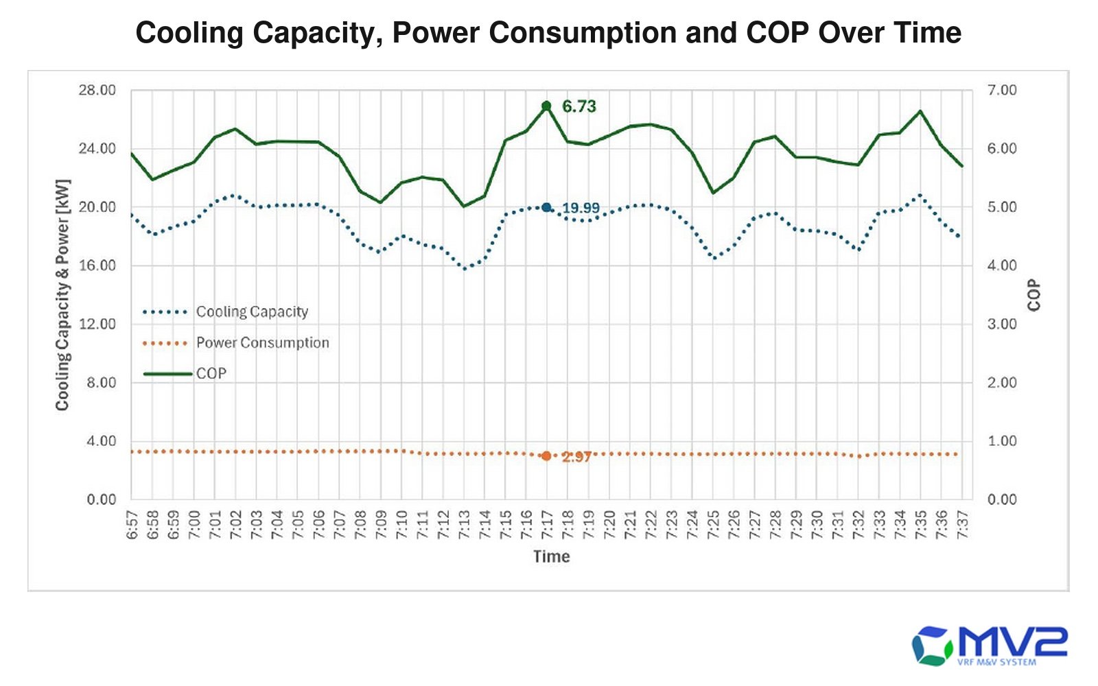
Line chart of a live MV2 measurement logged minute by minute over about forty minutes. Cooling capacity moves between roughly 16
A live MV2 record: cooling capacity, power consumption and COP logged minute by minute. Because all three are measured rather than assumed, COP can be followed as the load moves.
Technical characteristics

The measurements behind every result.

MV2 determines the actual cooling output of a VRF system using measured refrigerant enthalpy, refrigerant flow and electrical power.

The methodology is developed with reference to ISO 5151:2017, while the system’s measurement uncertainty has been independently verified by A*STAR’s National Metrology Centre.

Measured performance
Cooling capacity, power consumption and COP
Measured parameters
Flow, temperature, pressure and power
Measurement accuracy
≤10% uncertainty, verified by A*STAR NMC
Measurement options
Permanent monitoring or non-intrusive spot measurement
Data output
Real-time and historical performance data
Data access
USB, local portal, BMS or cloud platform
Compatibility
Suitable for different VRF brands
Reference standard
ISO 5151:2017
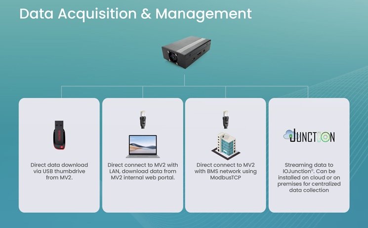
Data acquisition and management diagram. The MV2 unit branches to four routes: direct data download via USB thumbdrive; direct c
Four ways to get the data out: a USB download, a LAN connection to the MV2 web portal, ModbusTCP into a BMS network, or streaming to IOJunction on cloud or on premises.
Applications

Where MV2 can be applied.

MV2 is suitable wherever the actual operating performance of a VRF air-conditioning system needs to be measured, verified or improved.

Performance verification

  • New VRF system commissioning
  • Post-installation performance verification
  • Cooling-capacity and COP assessment
  • Verification of energy-efficiency claims
  • Brand & system efficiency comparison

Energy optimisation

  • Investigation of high energy consumption
  • Identification of inefficient operating conditions
  • System tuning and control optimisation
  • Before-and-after retrofit comparison

Compliance and certification

  • Green Mark measurement and verification
  • Energy audits and sustainability assessments
  • Performance-based contractual verification
  • Measurement support for energy-saving projects
The nine applications

Select any photograph to open it at full size.

Connected work

Measurement is the start of the work, not the end.

Service

Energy Audit & OSE

MV2 data feeds the baseline and the prioritised improvement roadmap.

View service

Solution

Distributed pumping

Once you can measure demand, you can match flow to it.

View solution

Find out what your VRF system is really doing.

Talk to us